Mechatronic System Design
Learning Objective
The learning objective of ME456 is for students to understand the entire process of developing a mechatronic
system. This includes a) system modeling, b) PID control, c) control implementation to the Arduino platform
using Simulink, and d) experimental validation. The class will also help students to understand the principles of
commonly used mechatronic system hardware, such as rate gyro and accelerometer sensors, DC motor actuators,
micro-controllers, etc., basic Simulink program development for Arduino compatible hardware, analyze system
output performance, and tune PID controller to satisfy certain output performance in simulations and experiments.
Mechantronic System Used for the Lab Sessions
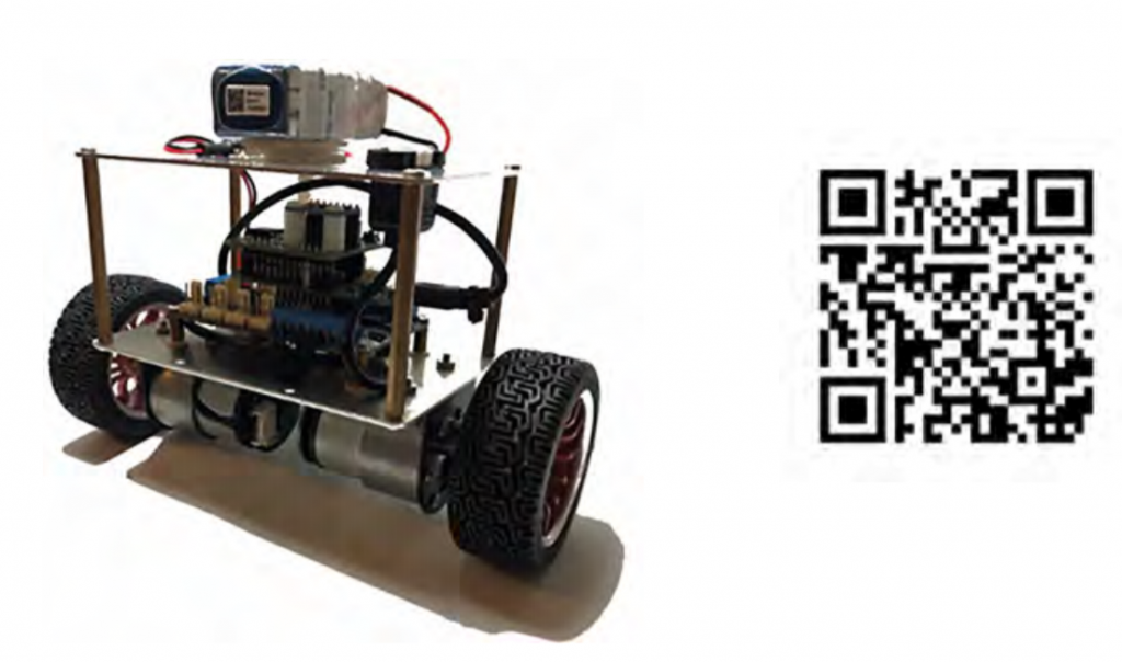
An Arduino-based Mini Segway robotics (see figure) will be provided to each student who may use his/her own
laptop (with installed Matlab/Simulink and Arduino library developed by MSU) to interface with the Mini Segway
through Wi-Fi network. The Mini Segway is equipped with two geared DC motors and position (speed) feedback
used to balance and drive the vehicle, and it is also equipped with gyro and accelerometer sensors to measure the
Mini Segway angular position and velocity. Note that the gyro and accelerometer signals will be processed to
generate Mini Segway pendulum angular position. Students will program the Arduino microcontroller in Simulink
and compile the Simulink-based software into Arduino automatically. The only programming knowledge required
for the class is Simulink that will be taught in Lab 1. For interested students, a GUI (graphic user interface) can be
created in Simulink to be used to control the Mini Segway and tune the PID gain in real-time. Please use this link
(https://youtu.be/fa6hp2grxrk) or scan the QR code below for a Mini Segway demo.


