Electrical Engineering
Projects
Electrical and Computer Engineering ECE 480 Senior Design is required of all electrical and computer engineering majors at MSU.
For information on becoming a project sponsor, please contact Gregg Motter.
The following are the project sponsors and projects for the spring of 2013:
![]()
Robert Bosch L.L.C.: Automated Power Mode Test System
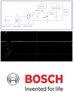 Robert Bosch L.L.C. must ensure safe and reliable operation of its infotainment ECUs under a variety of vehicular power modes. The transient responses included in these various power modes could cause unexpected behavior, and therefore it is imperative that the ECUs can be thoroughly tested in an easily automated way. One critical power mode is CRANK whereby the engine is usually started. The power supply our team is designing allows for simulation and testing of various CRANK profiles and their effect on the infotainment ECU in a scriptable, easily extensible, and modular fashion.
The CRANK profiles are loaded into a Microsoft C#.NET GUI application running on a Windows XP/Vista/7/8 operating system. These profiles are broken into voltage versus time metrics, and sent over USB to a PIC18F microcontroller. From within the Windows application, different profiles can be loaded and started/stopped in a scriptable fashion allowing for automated overnight testing of an infotainment ECU.
Once the voltage versus times metrics have been sent to the PIC18F microcontroller, the duty cycle required to achieve these metrics is calculated using on-chip firmware programmed in C. The microcontroller then sends pulses in the MHz range to the p-channel MOSFET pin on a Buck DC/DC regulator in order to realize these voltage versus time outputs. The Buck DC/DC is powered with DC power, which was converted from AC by an AC/DC regulator connected to a transformer. Internal traces from the device under test (DUT) are then sent back to the Windows application for analysis.

Team Members (L to R): William Novak, Nathan Hufstetler, Yuelei Ding, Chris Archambo, Jae Lee
![]()
Dr. Daniel Morris, 3D Vision Lab: Automated 3D Model Building
With the widening availability of RGB-Depth cameras to industry and to consumers, new applications for these sensors are in high demand. World modeling is one such application and, while done before in various research projects, the process of using RGB-Depth cameras to model a space has yet to become an automated process. Automating this process would allow for numerous practical applications ranging from military use to helping those with physical disabilities.
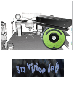 The goal of this project is to combine a robotic moving platform and a commercially available RGB-Depth camera to autonomously build a 3D model of a room. The combined device will require additional structural supports and power. A successful device will be able to localize its position when capturing images and integrate images together to build a 3D model. The robot should be able to completely map a room without getting stuck or running out of power and should do so in a timely manner.
Several challenges had to be addressed while working on this project including integrating the various pieces of hardware together, solving the mapping and localization problem, and combining the data from the RGB-Depth sensor into a cohesive and complete 3D model in real-time.
Pictured on right: an example of a 3D model of a room, along with both the RGB-Depth sensor (Microsoft Kinect V2) and robotic platform (iRobot Create 2) used in the project.

Team Members (left to right): Jacob Kneibel, Nick Zuzow, David Zoltowski, Kexiang Qian, Nick Saxton
![]()
US Agency for International Development: Low Cost Wireless Agricultural Sensors
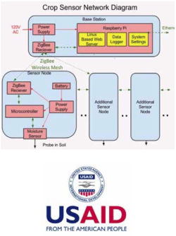 This project detects soil moisture levels across a small farm and uses a mesh communication network to relay information back to a central hub that will analyze the data and alert a user when the field needs to be watered.
Agriculture is an important part of many developing nations economy, especially in places such as Africa where water and fertilizer can be in short supply. Using resources as efficiently as possible is critical for farmers.
Our sensors will use a Zigbee based wireless protocol to create an ad hoc network and will use a Raspberry Pi as a computing solution for the hub that collects and processes the soil data.
This network requires sensors that are low power, inexpensive and have the battery life of a growing season which is typically around three months. The network as a whole also needs to be scalable to fit the needs of various field sizes. The case that will encapsulate the circuitry connecting the sensor to the network will need to be robust to moisture, dust, wild life and theft.
Upon completion of this project our team will be traveling to Tanzania through an MSU Study Abroad experience to install our system in a small farm run by a school for the Maasai in Mto wa Mbu where they grow a mixed crop of corn an bananas.

Team Members (L to R): Anthony Bird, Paul Solomon, Jennifer Byford, Scott Oliver, Andrew Warner
![]()
Texas Instruments: Electrocardiogram (ECG) Demonstration Board
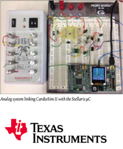 Portable and low power electrocardiogram (ECG) systems are in high demand in today’s technological markets. Many industries in the biomedical and engineering fields utilize ECG systems to diagnose heart conditions or monitor the vital signs of patients. Cardiologists, in particular, specialize in the interpretation of ECG signals. Their experience and knowledge of heart behavior allows them to correlate certain irregular signal patterns with diseases or health conditions.
Electrocardiograms are able to sense the small electrical signals produced by the muscles in the heart. These measurements are typically measured indirectly from the skin using electrodes. Signals produced by the heart are very small and need specialized equipment to obtain accurate display. Depending on the specific use of the equipment, many ECG monitors utilize digital signal processing as well as stable and well-designed analog signal conditioning. Noise and other electrical interference make these measurements challenging.
The Precision Analog group at Texas Instruments has proposed the challenge to design the analog circuitry required to interface a portable simulator (CardioSim II) with a Stellaris Evaluation Board (Oscilloscope). Texas Instruments plans to use the board for demonstration purposes only.
After designing, simulation, fabricating, and testing the demonstration board, the team’s portable solution is capable of measuring and displaying a reliable and low noise ECG signal.

Team Members: Mike Mock, Xie He, Yuan Mei, Nate Kesto, Chaoli Ang, Justin Bohr
![]()
ArcelorMittal: Crane Collision Avoidance
ArcelorMittal has been the world’s leading steel and mining company for many years. Present in over 60 countries, ArcelorMittal has established a sustainable foundation, working proficiently and focusing on the safety of their members. Priding themselves on the significantly low rate of injuries that take place inside of the facilities, ArcelorMittal has implemented their “Journey to Zero” campaign to completely alleviate any workplace incident in the future.
 In order to accomplish their “Journey to Zero,” the installation of a crane collision alert system warning an operator of any hazards, is an immediate need at the East Chicago, IN facility. Our team was given the task of designing a collision alert system that will provide an audible and/or visual alarm to the operator as the Electric Overhead Cranes (EOT) approaches a hazard at the same elevation as the crane.
Our collision avoidance system is comprised of two mechanisms: sensing technology and alert system. Using a proximity sensor, it will detect the distance between itself and another crane. Once the cranes come within a close proximity of one another, an alarm will trigger and this process will continue with a more intensified alarm every 50ft to alert the crane operator from colliding with another crane.

Team Members (left to right): Marcel Cochran, Joshua Johnson, Hang Zhao, Wenbo Gong, Le He, Keyon Clinton
![]()
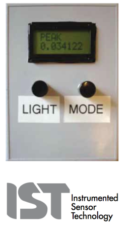
Instrumented Sensor Technology (IST): Real Time G-Meter with Peak/Hold
 Have you ever wondered what kind of forces your package receives when being shipped across the country? Integrated Sensor Technology (IST) has an idea to attach a G-meter (no larger than a cell phone) to a package to measure the G-forces received by the package during transit.
IST is sponsoring this senior design team and assigned the team to design and build a portable G-meter (similar to the meter pictured on the right) that can be placed on a shipped package. The G-meter is built to last a minimum of 30 days and run on two AA batteries.
The G-meter displays data in two modes. The first mode displays the current force that is acting on the meter. The second mode displays the maximum force that the G-meter has experienced the entire time that it has been active. The second mode also displays the date and time at which the maximum force occurred. This G-meter is designed to measure G-forces between positive and negative 17g.
The G-meter is composed of three main components: an accelerometer, a microcontroller, and an LCD screen. The accelerometer is the device that actually measures the G-force. The microcontroller is the device that takes the accelerometer’s measurement and formats it to display on the LCD screen. The microcontroller used in this G-meter is the TI MSP430 from Texas Instruments. This microcontroller is used because it can operate at a low power and can easily interface with an accelerometer and an LCD screen.

Team Members (L to R): Corey Fox, Eric-John Kohler, Timothy Carroll, Karl Anderson, Dan Svoboda, Shuhan Chen
![]()
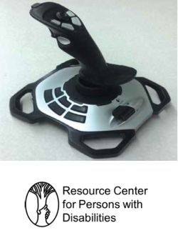
MSU Resource Center for Persons with Disabilities: Smart Voting Joystick for Accessible Voting Machines
 Research findings prior to a single axis joystick have indicated that people with disabilities are less likely to vote than individuals who do not have disabilities (statistics show 7% of the disability population in the survey conducted are less likely in 2008 and 3% less likely in 2010). Based on the above findings, the Resource Center for Persons with Disabilities (RCPD) of Michigan State University has requested an accessible smart double axis joystick with an integral display that can be used to operate electronic voting machines at voting precincts across the United States.
Design Team 5 has been assigned with developing the double axis joystick with an integral display for a voting ballot on a computer system that will provide individuals with disabilities to successfully vote without significant discomfort and within a reasonable amount of time compared to a standard voter without such disabilities.
The developed double axis joystick has USB connectivity and has been implemented with a haptic feedback control to enhance user interactions with a standard graphical user interface (GUI) paradigm. While standard joystick devices are input-only, haptic feedback control utilizes the sense of touch in a user interface design to provide information to an end user. Another feature that has been implemented in the joystick is a detented feature, which allows our user to more efficiently remain on a selected option without being impeded by any disabilities.

Team Members (L to R): Behdad Rashidian, Yangyi Chen, Tyler Dennis, Joy Yang, Graham Pence
![]()
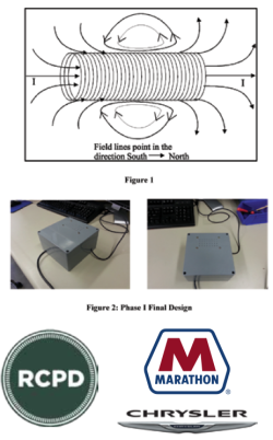
MSU Resource Center for Persons with Disabilities: Haptic User Interface Phase II
 Jordyn Castor is like a typical college student in many ways. A sophomore Computer Science major from Rockford, Michigan, she enjoys reading, listening to
music, and hanging out with family and friends. However, unlike most other students, Jordyn has been blind since birth. For the past 20 years, Jordyn has struggled with and overcame many challenges that result from being blind. As technology continues to advance and more everyday operations are handled via computers, new challenges arise for Jordyn and millions of other blind students. One of these particular challenges that our design team is addressing involves translating graphic images from a computer screen to a device that Jordyn or other blind students could interpret.
Though devices to aid visually impaired individuals with computers currently exist, they often range from $5,000- $10,000. Some read text aloud to enable the blind to navigate through windows. Others generate a raised surface of the images, from the computer screen, that users physically feel via touch. Our design is similar to this; however, there are some fundamental differences. The main goal of the project is to make an equally functional product that is more affordable compared to the devices that are on the market today.
Our solution to the design implements solenoids magnetically charging metal bars that raise and lower pins through voltage pulses. The pins latch in the raised or lowered positions depending on the polarity of the bars. Figure 1 shows an example solenoid and the magnetic field.

Team Members (L to R): Derek Brower, Matt Affeldt, Phil Jaworski, Jung-Chun Lu, Alex Volinski
![]()
Department of ECE: Autonomous Target Tracking Robot
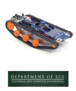 The purpose of this project is to design and build a robotic vehicle capable of autonomously identifying and following a marked target using a visual camera. The robot is remotely controllable for navigation to and from the target area using a commercially available Bluetooth joystick. It includes an autonomous mode where it searches a 360 degree field of view for a predefined target using the OpenCV C++ library to process the video stream from the camera. Upon successful target acquisition, the robot will close to within three feet of the target while avoiding collision. If the marked object moves the robot will be capable of autonomously following its motion. The robot is self-powered for over one hour of continuous run time. The robot is powered by a Lithium Polymer battery. It is capable of speeds around five mph and has a zero turning radius. An Arduino microcontroller is utilized to autonomously control all aspects of the robot including wheel movement, motor power, and direction. The device is capable of two-way communication with a simple portable “base station” such as a laptop, in order to accept commands and return data. This is achieved by implementing both WiFi and Bluetooth technologies. In addition to the primary collision sensors, other sensors are needed to collect additional data, such as wheel speed and target range. The chassis is structurally sound and is able to protect the electronics from minimal environmental conditions, with primary operation indoors at room temperature. Finally, an easily accessible manual shutdown switch is built into the robot that can cut power to the motors for safety purposes.

Team Members (L to R): Ted Schriefer, Brent Eisenmann, Matthew Beutlerm Hisham Hassan, Peng Xie, Victor Abreu
![]()
Air Force Research Laboratory: Motion Capture for Runners
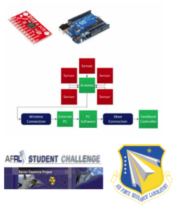 The team is tasked to design and test a product to capture running motion. This product analyzes the form of a runner and compares it to an elite runner under various running conditions. Sponsored through the Air Force Research Laboratory, the team is challenged to find an innovative and low cost solution to capture and analyze motion. They hope to use this technology to further understand motion of flexible structures of aircraft and spacecraft.
The objective of this project is to design a motion capture device that can be worn by runners in order to improve running efficiency. Inertial Measurement Units (IMUs) are sensors used to capture the runner’s movement. These sensors are placed within a universal body-suit to fit various body types. A body-worn microcontroller temporarily stores and performs preliminary processing of the raw data. The data is transmitted through wireless communication, processed on a PC, and compared with elite runner data. This processing is done in real-time, giving the runner immediate feedback. A body-worn indicator informs the runner on proper or improper running form.
This product is used inside on a treadmill, due to restrictions on wireless communication distances. The comparison software is utilized to process the data and perform analysis on efficiency of running form. Given accurate and real-time feedback, the runner is capable of maximizing their running technique

Team Members (L to R): Chenli Yuan, Alex Mazzoni, Zhichao Lu, Nori Wilkins, Blake Frantz, Dan Zilinskas
![]()
Fraunhofer CCL: Diamond Optics Measurement System
 In many avenues of modern engineering, diamond is an up and coming material. Diamond is one of the hardest substances known to man, is chemically inert, and has a very wide spectral window for transmission of light. In fact, Fraunhofer CCl grows diamonds right here on campus. In order to better measure and understand the imperfections of diamond, Fraunhofer CCL commissioned for a better measurement tool. This will allow Fraunhofer CCL to make better diamonds for future engineering technologies.
Since impurities in diamonds can be extremely small compared to the sample in general, a very precise instrument is needed. The basic idea is to have a light source, or laser, check and model impurities in diamonds with the assistance of polarizers. When the light goes through a polarizer, the light wave is filtered to travel in one direction. When the light interacts with a second polarizer which is at a 90 degree angle from the first, the light wave will be canceled out completely since both directions of the light wave have been filtered. A diamond with no impurities will allow light to pass completely through it. Thus, when placed between the two polarizers, there should be no visible light measured past the second polarizer. If there is, the light that went through the diamond was refracted off some impurity or stress in the diamond causing the direction of the wave light to change and not be filtered by the second polarizer. Our measuring device will calculate the coordinates of the impurities and provide a model of the diamond with the location of the impurities.

Team Members (L to R): Jessica Oakes, David Stiles, Mohamed Rosham, Afif Alsinan, Thomas Rex
![]()
Fanson Controls & Engineering: Parts Measurement System
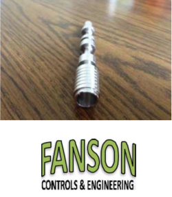
Fanson Controls and Engineering works closely with various manufacturing facilities to improve machine operation and control systems. Team 10 has been assigned a project from Fanson Controls and Engineering to create a parts measurement system for a transmission value (pictured on right) that is sold to various automobile manufacturers. By automating the quality control process, certain part specifications can be verified immediately after manufacturing of the part is complete. The system will increase the percentage of acceptable parts by giving immediate feedback to the operator to make manufacturing changes. Reduction of bad parts will minimize the cost of each part.
The parts measurement system implements a conveyor belt system that moves the part along a series of sensors. The part is held firmly in place with the use of a cleated conveyor belt and side railings. Sensors are mounted to the sides of the conveyor system and record measurement data as the parts pass through. The sensors measure total length, end-hole depth and diameter, and verify double broaching at the end of the part. A Programmable Logic Controller (PLC) is used to control the belt and sensor movement and to interpret analog and digital data from the sensors. If a part does not meet the required specifications, the PLC signals a solenoid to remove the part from the conveyor system. If requirements are met, the part continues to the end of the belt and falls into a bin with the other accepted parts. The system will allow for future upgrades and additions to be made by Fanson Controls and Engineering.

Team Members (L to R): Jared Jones, Mark Holzhauer, Eric Martz, Nolan Boyda, Justin Walz
![]()